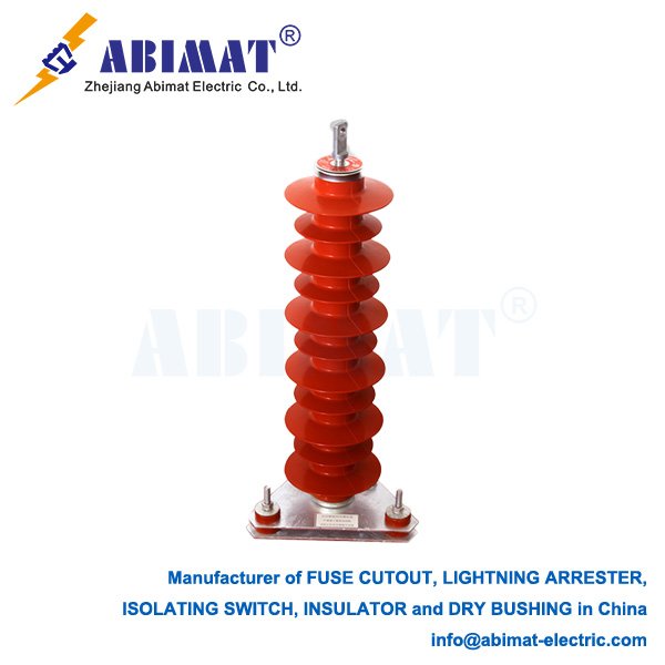
Technical Overview of 69 kV Metal Oxide Arresters for Power System Protection
Lightning arresters are critical for safeguarding medium-voltage power systems (e.g., substations, transmission lines) against transient overvoltages from lightning strikes or switching events. For 69 kV systems, –metal oxide arresters (MOAs)– dominate modern applications due to their superior energy absorption and rapid response characteristics.

Core Technical Specifications
The rated voltage is 69 kV. It matches the system’s operating voltages, keeping things stable during normal use and when faults happen.
Continuous operating voltage (Uc) has to be higher than the system’s maximum phase-to-ground voltage. For 69 kV systems, this is usually at least 40.3 kV.
Discharge current capacity has a standard 10 kA rating for normal discharge current—this uses an 8/20 μs waveform. It can handle up to 100 kA for bad surges.
The protection level limits residual voltage to 2.5 kV or less during surges. This keeps the insulation of downstream equipment in good shape.
Leakage current stays below 50 μA at 0.75 times the DC reference voltage. This shows the insulation is healthy and there are few losses from wear.
Design & Material Advancements
Modern 69 kV MOAs use zinc oxide (ZnO) valve elements. These elements have a highly nonlinear resistivity, letting them conduct surges passively without needing series gaps.
The housing is made of silicone rubber composite, which has several benefits. It is hydrophobic—methyl groups in the material repel moisture, cutting down on flashovers caused by pollution. It is also lightweight: 69 kV units weigh about 50 kg, much lighter than porcelain versions that can hit 260 kg. This makes installation easier.
Another plus is pressure relief. Wedge-notched fiberglass tubes and explosion-proof designs help safely release internal arcs when faults happen.
Performance Validation & Standards
Strict testing follows GB/T 11032-2018 and IEC 60099-4. One key test is the high-current test: they handle 100 kA lightning impulses (8/20 μs) and 4/10 μs high currents without failing.
Residual voltage tests check how well they protect equipment. These tests use 1/10 μs steep waves and 30/60 μs switching surges to measure their effectiveness.
Long-term stability is also verified. The temperature coefficient is no more than 0.05% per °C, so they work consistently even when temperatures range from -40°C to +85°C.
Installation & Field Considerations
Grounding is important. The ground resistance should be no more than 10 Ω in most cases, or 30 Ω in areas with high resistivity.
Connection geometry matters too. Phase and ground leads need to be 1 meter or shorter to keep inductance low. Sharp bends should be avoided.
Monitoring is required. Every year, before the monsoon, check for visible damage or sudden increases in leakage current.
Conclusion
Abimat 69 kV MOAs offer strong protection against overvoltage. They use advanced ZnO technology and polymer housing to do this. Following standard tests—like those in GB/T 11032—keeps them reliable in both utility and industrial settings.
Good grounding and regular maintenance help keep the system strong. Looking ahead, there’s a trend toward adding IoT sensors. These will monitor wear in real time.


