115 kV Disconnecting Switches: Technical Specifications and Applications
Disconnecting switches (isolators) serve as critical safety components in 115 kV substations and transmission networks. These devices provide visible circuit isolation for maintenance, system reconfiguration, and grounding operations. Unlike circuit breakers, disconnecting switches do not interrupt load current or fault current.
Primary Functions
The visible air gap creates a physical isolation space—over 1.5 m for 115 kV systems. It confirms the power is off, following IEC 62271-102 rules.
Integrated grounding blades, whether manual or motor-run, safely release trapped electricity to the ground.
They handle continuous current, usually 1,250–2,000 A, and short bursts too—like 40 kA RMS for 3 seconds.
They pass standard dielectric tests: 230 kV AC for power frequency and 550 kV for lightning impulse.
Common 115 kV Configurations
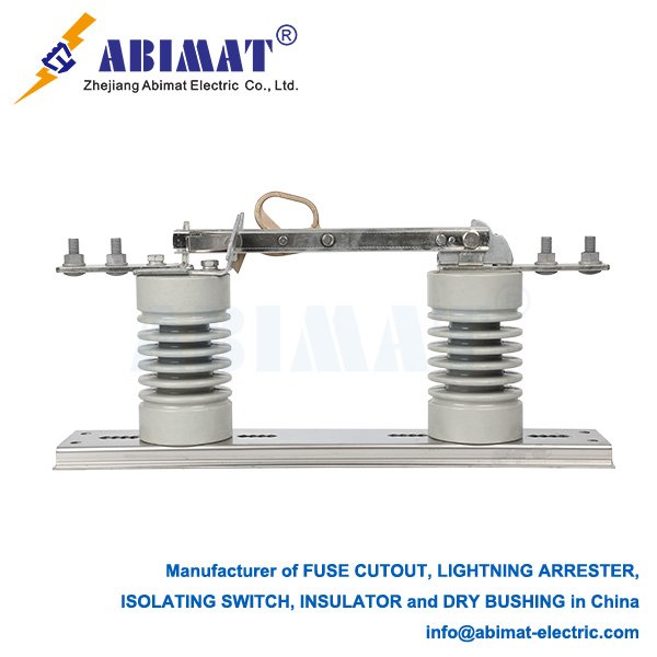
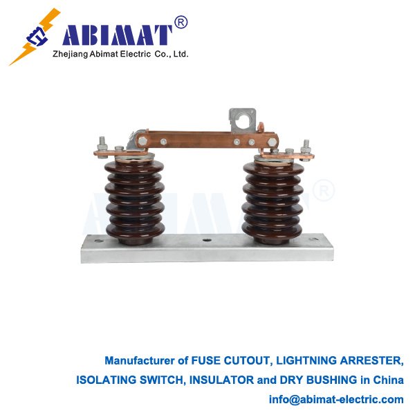
Center-Break Horizontal Rotary (Double-Access) has rotating blades that open and close horizontally. It’s standard for bus connections needing at least 2.5 m between phases. It can handle radial ice loading of 20 mm or more, as per IEC 62271-3.
Vertical-Break (Single-Access) uses vertically moving blades, which take up less space. It works well for linking GIS to overhead lines.
Pantograph Type has collapsible arms, saving space. You’ll often find it in transformer bays.
Construction Features
The conductive path uses aluminum alloy blades with silver-plated contacts. These keep contact resistance below 100 µΩ.
Insulation systems—porcelain or composite hollow-core insulators—offer a leakage distance over 31 mm/kV for Pollution Class IV.
Operating mechanisms have motor drives, either DC 110V/220V or AC 380V, and include manual override. Torque monitoring stops mechanical damage when ice jams things up.
Safety Interlocks: Mechanical and electrical systems stop certain actions. They prevent switch operation when the grounding blade is engaged. They also stop grounding on circuits with power.
Installation & Maintenance
You need to keep clearances: at least 2.5 m between phases and 2.0 m from phase to ground, following IEEE C37.32.
Cold climates need anti-icing coatings or heater kits for operation.
Arcing horns control induced capacitive currents—keeping them below 0.5 A.
Validation testing includes a few key checks: measuring contact resistance (Ductor test), making sure open/close timing is 10 seconds or less, and running power frequency dry and wet dielectric tests.
Operational Safety
Voltage detection—optional indicators—confirms the power is off.
Inspections use annual infrared thermography. It spots abnormal heating, when things get more than 10°C hotter than the surrounding air.
Preventive maintenance means lubricating pivot points. Use silicone-based grease, and do this every 5 years.
Primary Applications
They isolate 115 kV transformers, circuit breakers, and bus sections.
They help split transmission lines to isolate faults.
They set up safe grounding points for maintenance crews.
Summary
Abimat 115 kV disconnecting switches give critical visible isolation in high-voltage networks. Their design is engineered to work—combining clear air gaps, high current capacity, and insulation that resists pollution. This ensures they stay safe to use even in extreme electrical and environmental conditions.
Choosing the right switch, installing it properly, and keeping up with maintenance stops dielectric failures and mechanical jams. This helps keep the grid reliable.