
Fuse Link Cut-Outs: The Workhorse of Overhead Distribution Protection
Introduction
Fuse link cut-outs are indispensable, robust, and cost-effective protective devices in overhead electrical distribution systems (typically up to 38 kV). Often called “distribution cutouts” or simply “fuse cutouts,” they serve two critical functions: providing reliable overcurrent protection for key assets like transformers and feeders, and acting as a visible, manual disconnecting point for safe circuit isolation during maintenance. Their enduring presence highlights their fundamental value in utility infrastructure.
Core Function: Precision Interruption
The primary function of a fuse link cut-out is precise: to detect and safely interrupt excessive current flow caused by faults (short circuits or damaging overloads) within its protective zone. This action is vital for:
I. Asset Protection: Shielding downstream equipment, especially distribution transformers, from catastrophic thermal and mechanical damage due to fault currents.
II. System Integrity: Preventing fault currents from propagating upstream, minimizing outage scope, enhancing overall network reliability, and speeding fault location.
III. Safety: Providing a definitive, visible break for line crew safety during work.
Operating Principle: Controlled Arc Energy
Interruption relies on the physics of the fusible element and its environment:
I. Normal Load: Current flows unimpeded through the intact fusible element within its rated capacity.
II. Fault Detection: Current exceeding the element’s calibrated rating for a specific duration (defined by its Time-Current Characteristic – TCC) causes rapid Joule heating.
III. Element Melting: The fusible element melts (“blows”) at its weakest point, initiating an electric arc.
IV.Arc Management & Extinction: The arc forms inside the insulating fuse tube, lined with gas-generating material (e.g., fiberglass, boric acid). Intense arc heat decomposes this lining, producing high-pressure gases expelled forcefully through designed vents. This expulsion:
Elongates and cools the arc plasma.
Deionizes the arc path.
Extinguishes the arc and interrupts the fault current.
Creates a characteristic audible expulsion (“bang”).
V.Visual Indication & Isolation: After operation, the fuse holder assembly typically pivots downward (“drop-out” design) or displays a clear external indicator (e.g., melted target). This provides instant visual fault confirmation and establishes a safe, visible air gap isolating the downstream circuit—a crucial safety feature.
Key Components & Construction
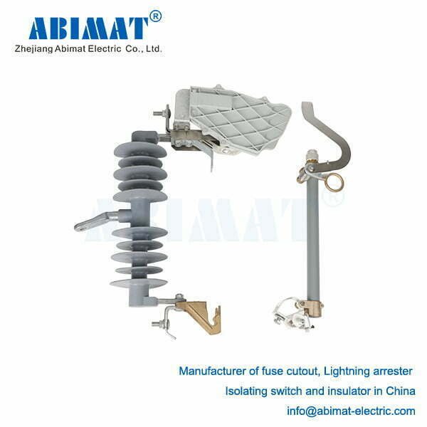
A cut-out is a robust assembly comprising:
I. Fuse Holder (Tube): The core insulating body (porcelain or modern polymer) housing the fuse link. Designed to contain arc energy, withstand weather, and channel expulsion gases downward or away safely.
II. Removable Fuse Link: The replaceable core of the device:
Fusible Element: Precisely calibrated wire/strip (Ag, Sn, Cu alloys) with a specific TCC for coordination.
Arc-Quenching Lining: Surrounds the element, generating extinguishing gases.
Strain Assembly: Maintains mechanical tension for reliable drop-out operation.
Terminals: Ensure secure electrical contact within the cutout body.
III. Cutout Body: The base assembly fixed to the pole or crossarm:
Insulating Support: Provides electrical isolation and mechanical strength.
Upper & Lower Contacts: Securely clamp the fuse holder terminals.
Hinge & Latch: Allows the holder to pivot open after fuse operation and enables easy link replacement.
IV. Mounting Insulator: Provides primary structural support and creepage distance.
Primary Applications
Fuse link cut-outs are ubiquitous for:
Transformer Primary Protection: The dominant solution for protecting pole-mount and pad-mount distribution transformers.
Feeder & Lateral Protection: Safeguarding main distribution feeders and branch circuits.
Sectionalizing: Dividing feeders into protected zones to limit outage impact and aid fault location/isolation.
Capacitor Bank Protection: Isolating faulted switched capacitor banks.
Tap Protection: Protecting circuits branching off main feeders.
Advantages: Simplicity and Effectiveness
Their enduring popularity stems from key benefits:
High Fault Interrupting Rating: Capable of clearing the high fault currents common on utility distribution systems.
Proven Reliability & Robustness: Simple, mechanical design validated over decades under harsh conditions.
Unambiguous Visual Indication: Instant operation confirmation (dropped holder/indicator) speeds fault finding.
Definitive Isolation: Creates a visible, safe air gap—essential for lockout/tagout (LOTO) procedures.
Cost-Effectiveness: Lower initial and maintenance cost than automated reclosers for many applications.
Rapid Service Restoration: Line crews can quickly replace a blown fuse link.
Critical Application Considerations
Effective use requires attention to:
Single-Interruption Device: Requires manual replacement after operation; unsuitable for temporary faults where autoreclosing is beneficial.
Protection Coordination: Meticulously select fuse link ratings and TCCs for selective coordination with upstream devices (reclosers, substation breakers) and downstream fuses/equipment, using coordination curves.
Environmental Impact: Ambient temperature significantly affects TCC (requiring correction factors). Wind, pollution, and altitude can influence performance and insulation.
Expulsion Characteristics: Requires adequate vertical and horizontal clearance for safe gas venting. Not suitable for indoor or confined spaces.
Mounting & Maintenance: Proper installation angle and periodic inspection/cleaning of insulators are vital for reliability.
Conclusion
The ABIMAT fuse link cut-out remains a cornerstone of safe, reliable overhead electrical distribution. Its robust construction, effective arc interruption, clear visual status, and safe isolation capability ensure its continued relevance. Despite protection technology advancements, its simplicity, cost-effectiveness, and proven performance make it the preferred choice for transformer protection and feeder sectionalizing. A thorough understanding of its operating principles, application nuances, and coordination requirements is fundamental for distribution engineers and technicians designing, operating, and maintaining resilient power networks. It stands as a testament to enduring, practical engineering.
