15 kV Disconnect Switches: Critical Components for Medium-Voltage System Safety
15 kV disconnect switches serve as fundamental safety devices in industrial power distribution, utility substations, and commercial electrical networks. Operating at medium-voltage levels, these components provide essential isolation functions for maintenance safety and system operation.
Primary Function: Visible Circuit Isolation
The core purpose of a 15 kV disconnect switch is to establish a visible air gap in the circuit. When open, separated contacts create unambiguous physical isolation between de-energized equipment and live sections. This fulfills critical requirements:
I.Personnel Protection: Creates a verifiable de-energized state for safe maintenance of downstream equipment (transformers, capacitors, feeders).
II.Operational Control: Enables circuit sectionalization, load transfers, and system reconfiguration without full network de-energization.
Design and Operational Characteristics
Voltage Rating: Designed for 15 kV systems with dielectric strength to withstand operating voltage, temporary overvoltages, and lightning impulses (standard BIL ratings: 95 kV, 110 kV, 125 kV).
Current Rating: Carries continuous load currents (typically 600A, 1200A, 2000A) without excessive temperature rise. Withstands specified short-circuit currents (e.g., 25-40 kA for 1-4 seconds).
Switching Limitation: Standard disconnect switches cannot interrupt load or fault current. Operation under load causes destructive arcing. They operate only after upstream circuit protection clears the circuit.
Specialized Interruption: Certain designs incorporate arcing horns to break minimal capacitive charging currents (unloaded cables/bus sections) per IEEE C37.34.
Configuration Types:
Indoor (Switchgear): Horizontal-drawout or vertical-break types within arc-resistant metal-clad compartments.
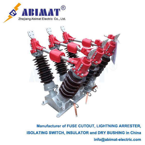
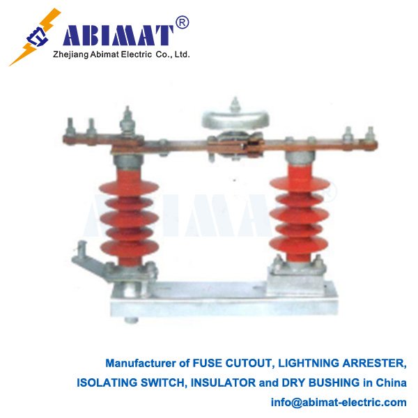
Outdoor: Vertical-break designs on poles/structures with weather-resistant construction.
Loadbreak Versions: Integrated vacuum interrupters enable load current interruption (disconnect-loadbreak combos).
Operation: Manual via rotary handle, lever, or push-pull rod (often spring-assisted). Motorized operators enable remote/SCADA control.
Safety Systems
Mechanical Interlocks: Prevent critical errors:
Opening disconnects with closed circuit breakers
Racking switches into energized compartments
Accessing live sections during maintenance
Closing grounding switches while disconnects are engaged
Grounding Provisions: Integral or companion grounding switches provide visible earthing of isolated sections, protecting against induced voltages.
Position Indication: Clear visual “OPEN”/”CLOSED” indicators.
Selection Criteria
Key selection factors:
Environment: Indoor (switchgear) vs. outdoor (pole/pad-mount)
Electrical Ratings: Continuous current, short-circuit withstand (kA/s), BIL
Duty Requirement: Isolation only or capacitive current switching
Mechanical Endurance: Required operating cycles
Site Conditions: Altitude, pollution, temperature, seismic zone
Control Method: Manual or motorized actuation
Compliance: IEEE C37.20.2 (Switchgear), C37.34 (Disconnects), or IEC 62271-102
Maintenance Imperative
Essential maintenance ensures reliability:
I.Contact Inspection: Verify alignment and erosion
II. Insulator Check: Detect cracks or contamination
III. Mechanical Test: Confirm smooth operation and full engagement
IV. Interlock Verification: Validate all safety sequences
V. Lubrication: Apply manufacturer-specified lubricants
Conclusion
The ABIMAT 15 kV disconnect switch remains indispensable for medium-voltage system safety. Its visible isolation capability protects personnel during maintenance while enabling operational flexibility. Robust construction, adherence to safety standards (particularly interlocks and grounding), and disciplined maintenance ensure reliable long-term performance in industrial and utility applications.