220kV Lightning Arresters: Guardians of High-Voltage Transmission Systems
Introduction
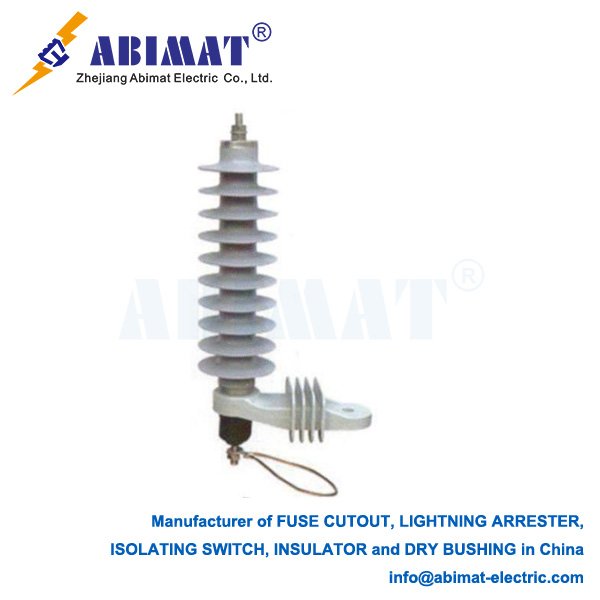
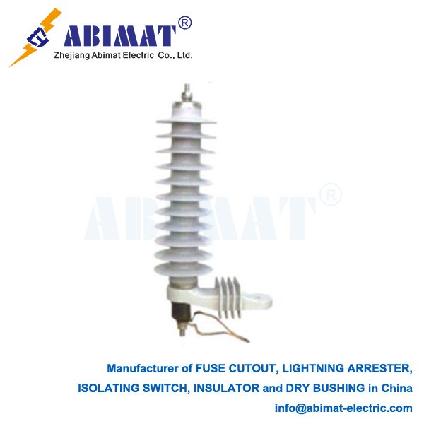
220kV lightning arresters (surge arresters) serve as critical protective components in extra-high-voltage (EHV) transmission networks. Operating at the backbone of national power grids, they defend multi-million-dollar equipment against transient overvoltages from lightning strikes, switching operations, and system faults. Their failure can cascade into widespread blackouts, making precise engineering and selection paramount for grid resilience.
Core Operational Principle
These arresters function as voltage-controlled switches between phase conductors and ground:
– High-Impedance State: At normal operating voltage (< threshold), they act as open circuits (leakage current < 1 mA).
– Low-Impedance State: During transient overvoltages, they switch to low resistance within < 100 nanoseconds, creating a low-impedance path to ground. Crucially, they clamp the residual voltage (Up) across protected equipment to a safe value below its Basic Lightning Impulse Level (BIL). Post-event, they autonomously reset.
Technology: Advanced ZnO Varistor Columns
Modern 220kV arresters utilize stacked Zinc Oxide (ZnO) varistor columns housed in porcelain or composite polymer housings. Each varistor disc contains ZnO grains doped with Bi₂O₃, Sb₂O₃, CoO, and MnO₂, forming billions of grain-boundary p-n junctions:
– Normal Voltage: Junctions act as barriers (high resistance).
– Surge Voltage: Electric field-induced quantum tunneling collapses junction resistance.
– Self-Restoration: Junctions reform post-surge
Key Advantages for EHV Applications:
– Ultra-nonlinear V-I characteristics
– Energy absorption capacity > 10 kJ/kV of Ur
– Response time ≤ 25 ns
– Zero power-frequency follow current
– Voltage grading rings optimize electric field distribution
Critical Performance Parameters & Selection
(Per IEC 60099-4 / IEEE C62.11)
| Parameter | Technical Significance | 220kV System Values |
|---|---|---|
| Rated Voltage (Ur) | Max temporary power-frequency overvoltage (10s withstand). Must exceed maximum Temporary Overvoltage (TOV). | 180kV–216kV (Ur ≥ 1.25 × nominal phase-ground voltage for effectively grounded systems) |
| MCOV | Max continuous RMS phase-ground voltage. Critical for thermal stability. | 146kV–160kV (For 220kV systems: Vₗ₋₉ = 127kV) |
| Nominal Discharge Current (In) | Standard 8/20 µs lightning current rating. | 10kA (Standard) 20kA (High lightning density) |
| Line Discharge Class | Energy handling from line switching surges (IEC). | Class 4-5 (≥ 20kJ/kV of Ur) |
| Lightning Impulse Protective Level (Up) | Max residual voltage at 8/20 µs current. Must be ≥25% below equipment BIL. | ≤ 550kV (For 1050kV BIL transformers) |
| Switching Impulse Protective Level (SPL) | Residual voltage at 30/60 µs or 100/1000 µs wave. | ≤ 450kV (Critical for breaker TRV coordination) |
| Steep Front Protective Level | Residual voltage at 1.2/50 µs wave (GIS close-in strikes). | ≤ 650kV |
| Pressure Relief Rating | Max short-circuit current withstand upon failure. Mandatory for safety. | 40kA–63kA (Matches substation fault level) |
| Creepage Distance | Pollution performance (IEC 60815). | ≥ 6,300mm (Very Heavy Pollution) |
Transmission-Specific Design Features
– Grading Rings: Control electric field distribution across multi-unit columns.
– Sealed Housing: Nitrogen/SF₆-filled porcelain or silicone rubber composite prevents moisture ingress.
– Explosion Containment: Porcelain housings include frangible caps; polymer uses fiber-reinforced burst membranes.
– Seismic Rating: Certified for ≥ 0.5g horizontal acceleration (IEEE 693).
Strategic Applications in 220kV Networks
I.Transformer Protection: Directly connected to 220kV bushings (BIL coordination essential).
II.Substation Entrances: First protection point for incoming transmission lines.
III.Shunt Reactor/Capacitor Banks: Suppresses switching surges during de-energization.
IV.GIS (Gas-Insulated Switchgear): Requires specialized low-Up arresters with steep front protection.
V.Long Transmission Lines: Installed at intervals > 500m to limit backflashover.
VI.Generator Step-Up (GSU) Transformers: Critical for power plant grid interfaces.
Selection Engineering Process
I.TOV Analysis: Determine maximum fault-induced overvoltage duration/magnitude → Set Ur.
II.Insulation Coordination: Ensure Up ≤ 75% of protected equipment BIL (e.g., 1050kV BIL transformer → Up ≤ 787kV).
III.Energy Calibration: Calculate prospective surge energy (lightning density × line length) → Select Line Discharge Class.
IV.Fault Current Verification: Match pressure relief rating to substation SC level.
V.Environmental Validation: Adjust creepage for site pollution severity (IEC 60815 Class IV).
Monitoring & Diagnostics
– Leakage Current Sensors: Track resistive component (Ic) increase – early indicator of ZnO degradation.
– Surge Counters: Log discharge events for maintenance planning.
– Thermal Imaging: Detect hot spots (>5°C above ambient indicates failure risk).
– Hydrophobicity Checks: For polymer-housed units (indicates aging).
Manufacturers like ABIMAT offer integrated IoT monitoring platforms providing real-time analytics.
Failure Prevention Protocol
– Annual thermographic scans
– Biennial leakage current measurements
– Immediate replacement if:
– Ic resistive component > 1 mA
– Housing damage/cracking
– Disconnector operation (if equipped)
Conclusion
220kV lightning arresters represent apex engineering in surge protection, combining advanced ZnO technology, rigorous insulation coordination, and robust mechanical design. Their correct selection—demanding precise calculation of Ur, MCOV, protective levels (Up/SPL), and safety ratings—directly impacts grid reliability. In an era of increasing extreme weather events, optimized arrester deployment, supplemented by predictive monitoring from manufacturers like ABIMAT, provides indispensable defense for critical transmission infrastructure against escalating surge threats.