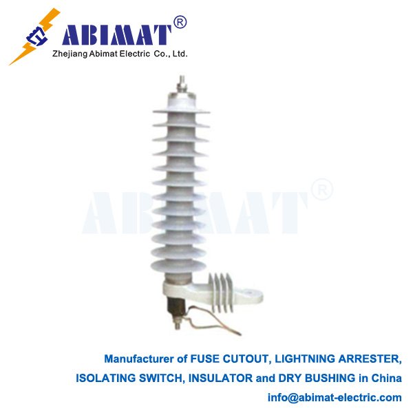
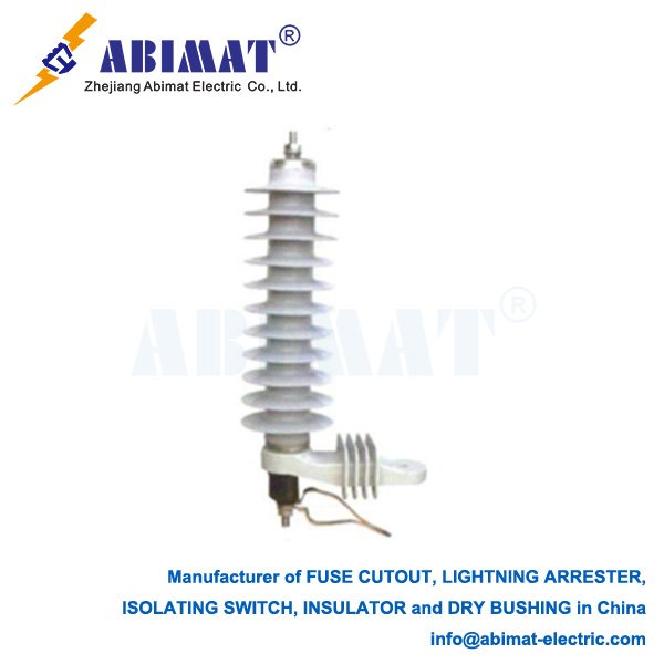
33 kV Lightning Arresters: Protection Against Transient Overvoltages
33 kV lightning arresters are essential components in medium-voltage power systems, safeguarding equipment from damaging voltage surges caused by lightning-induced and switching transients. These devices protect transformers, switchgear, and cables by limiting overvoltages to safe levels.
Operational Principle
Arresters perform three critical functions:
I. Voltage Monitoring: Maintain high impedance during normal system operation (33 kV phase-to-phase)
II. Surge Diversion: Instantaneously switch to low impedance during overvoltages, channeling surge current to earth
III. Voltage Clamping: Maintain residual voltage below the protected equipment’s Basic Insulation Level (BIL)
IV. System Recovery: Automatically restore high-impedance state after surge events
Key Technical Parameters
Rated Voltage (Ur): 30-36 kV (system-dependent), exceeding maximum continuous operating voltage
MCOV (Maximum Continuous Operating Voltage): 24-28 kV RMS (prevents thermal runaway)
Duty Class: Station (highest energy handling), Intermediate, or Distribution
Nominal Discharge Current (In): 5kA, 10kA, or 20kA (standard test rating)
Residual Voltage (Ures): Voltage at specified current (e.g., 10kA 8/20µs wave). Must be ≤85% of protected equipment BIL (typically 170-200 kV)
Energy Rating: kJ/kV Ur capacity (determines multi-surge withstand)
Pressure Relief: Withstands internal faults without casing rupture
Zinc Oxide (MOV) Technology
Modern 33 kV arresters employ gapless metal-oxide varistor technology:
– Non-linear Characteristics: Exponential voltage-current relationship
– Nanosecond Response: Faster operation than gapped designs
– High Energy Density: Superior kJ absorption per unit volume
– Hermetic Sealing: Prevents moisture ingress and contamination
– Monitoring Provisions: Terminal for leakage current measurement
Selection Criteria
- System Parameters: Temporary overvoltages, fault current magnitude
- Protected Equipment: Transformer/reactor BIL ratings
III. Location Criticality:
– Station class: Substation entrances, generator terminals
– Distribution class: Pole-mounted applications
- Environmental Conditions:
– Pollution severity (determines creepage distance: ≥31 mm/kV for Class IV)
– Altitude (>1000m requires derating)
– Seismic zone requirements
- Short-Circuit Withstand: Pressure relief capacity > available fault current
- Monitoring Needs: Leakage current measurement ports
Installation Requirements
Proximity: Mount directly adjacent to protected equipment
Earthing: Establish low-impedance earth connection (<5 Ω)
Conductor Practice:
– Keep lead lengths minimal
– Employ short, straight conductors
– Avoid sharp bends in downconductors
Clearances: Maintain phase-to-phase/ground distances per IEC 61936
Orientation: Install vertically unless designed for horizontal mounting
Maintenance & Monitoring
Visual Inspection: Quarterly checks for:
– Housing damage (cracks, tracking)
– Seal integrity
– Corrosion/birdcage damage
Leakage Current Measurement:
– Baseline reading at commissioning
– Trend resistive component (>20% increase indicates degradation)
Thermal Imaging: Annual IR scans under load
Diagnostic Testing:
– Insulation resistance (>1000 MΩ)
– Reference voltage tests (per OEM schedule)
Standards Compliance
Complies with:
– IEC 60099-4 (Metal-oxide surge arresters)
– IEEE C62.11 (Standard for MOV arresters)
– ANSI/IEEE C62.22 (Application guide)
Failure Mechanisms
Moisture Ingress: Degrades MOV blocks (detected via rising leakage current)
Thermal Runaway: Caused by continuous overvoltage or contamination
Energy Overstress: Exceeding rated kJ capacity
Seismic Damage: Cracked porcelain/polymer housings
Conclusion
Properly specified 33 kV metal-oxide arresters provide critical protection against transient overvoltages in medium-voltage systems. Their non-linear characteristics and rapid response ensure sensitive equipment remains within safe voltage tolerances during surge events. Rigorous adherence to installation practices, regular leakage current monitoring, and compliance with IEC/IEEE standards are fundamental to achieving reliable, long-term system protection and preventing catastrophic equipment failure.