220kV Lightning Arresters: Guardians of High-Voltage Transmission Systems
Introduction
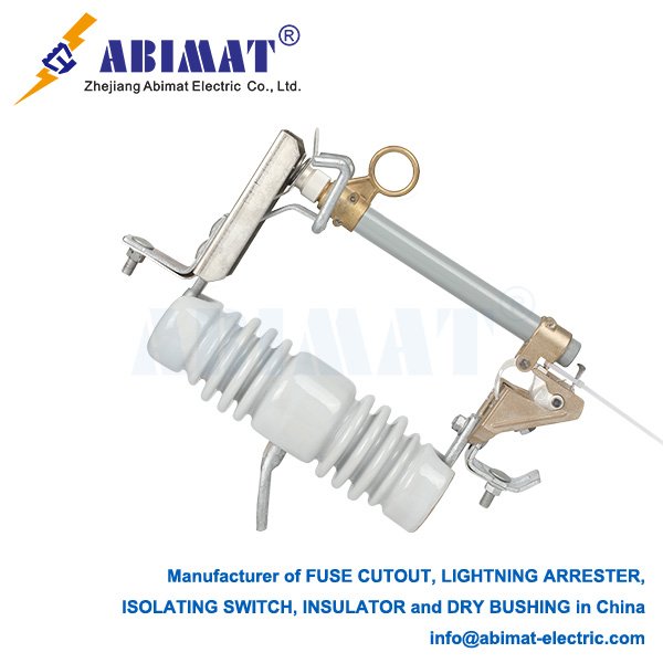
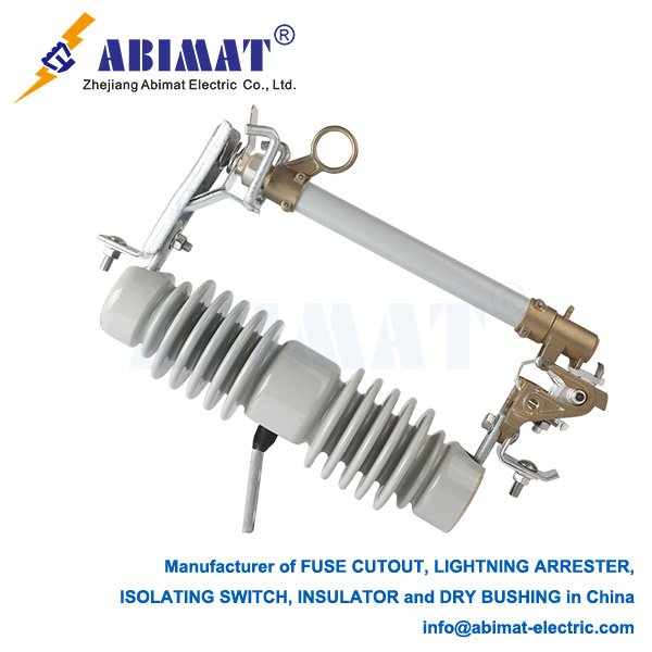
Fuse cutout links, commonly known as “distribution cutouts” or “fuse cutouts,” are fundamental protective devices found throughout overhead electrical distribution networks, typically handling voltages up to 38 kV. They serve two critical purposes: providing reliable overcurrent protection for transformers, feeders, and laterals, and acting as a clear, manual disconnecting point for circuit isolation and maintenance. Their robust design and operational simplicity make them indispensable components of utility infrastructure.
Core Function and Operating Principle
The primary role of a cut-out fuse link is straightforward: to safely interrupt excessive current caused by faults (such as short circuits or sustained overloads) within the protected circuit segment. This action protects downstream equipment like transformers from severe damage and prevents fault currents from spreading, enhancing overall system reliability.
Operation relies on a precisely calibrated fusible element housed within the removable fuse link assembly:
I.Normal Operation: Under normal load current within its rated capacity, the fusible element remains intact, allowing uninterrupted power flow through the fuse holder (fuse tube).
II.Fault Condition: When current exceeds the fuse link’s rating for a predetermined duration, the fusible element rapidly melts (“blows”) due to Joule heating.
III.Arc Initiation & Extinction: Melting the element initiates an electric arc inside the fuse tube. The tube, often lined with a deionizing material such as fiberglass or boric acid, generates gases under the intense heat of the arc. This gas generation creates high internal pressure.
IV.Expulsion Effect: The pressurized gases are expelled forcefully through vents at the bottom or ends of the tube. This controlled expulsion elongates, cools, and deionizes the arc plasma, effectively quenching it and interrupting the fault current. The gas expulsion often produces a noticeable audible report (a “bang”).
V.Visible Indication & Isolation: After operation, the fuse link assembly visibly drops open (in “drop-out” style cutouts) or shows other clear external signs (like a melted indicator). This provides immediate visual confirmation of operation and creates a safe, visible air gap isolating the downstream circuit.
Key Construction Components
I.Fuse Holder (Tube): The insulating housing (typically made of porcelain or polymer) contains the fusible element and arc-quenching medium. It’s designed to withstand arc energy and channel the expulsion gases.
II.Removable Fuse Link: This core component includes:
Fusible Element: A precisely engineered wire or strip (e.g., silver, tin, copper) with a specific time-current characteristic (TCC).
Arc-Quenching Medium: Lining material surrounding the element that generates arc-extinguishing gases.
Strain Wire/Assembly: Provides mechanical tension to ensure proper operation and drop-out.
Terminations: Electrical contacts for connection within the cutout body.
III.Cutout Body (Mounted Assembly): The base assembly mounted on the pole or crossarm, typically consisting of:
Insulating Bracket/Housing: Supports the fuse holder and provides electrical insulation.
Upper & Lower Contacts: Clamp onto the fuse holder terminals to connect it in series with the circuit.
Hinge & Latch Mechanism: Allows the fuse holder to pivot open after operation and facilitates easy insertion and removal.
IV.Mounting Insulator: Provides structural support and electrical isolation from the pole or structure.
Primary Applications
Cut-out fuse links are primarily used for:
Transformer Protection: Protecting pole-mounted and pad-mounted distribution transformers.
Feeder/Lateral Protection: Safeguarding main distribution feeders or branch laterals from faults.
Sectionalizing: Dividing circuits into protected zones to minimize outage impact and aid fault location.
Capacitor Bank Protection: Protecting switched capacitor banks on distribution circuits.
Tap Protection: Protecting circuits tapped off a main feeder.
Transmission-Specific Design Features
– Grading Rings: Control electric field distribution across multi-unit columns.
– Sealed Housing: Nitrogen/SF₆-filled porcelain or silicone rubber composite prevents moisture ingress.
– Explosion Containment: Porcelain housings include frangible caps; polymer uses fiber-reinforced burst membranes.
– Seismic Rating: Certified for ≥ 0.5g horizontal acceleration (IEEE 693).
Advantages
High Interrupting Capacity: Capable of safely interrupting very high fault currents common on distribution systems.
Reliable & Proven: Simple, robust, and time-tested technology.
Clear Visual Indication: Provides unambiguous confirmation of operation and fault location.
Effective Isolation: Creates a visible, safe air gap essential for maintenance safety.
Cost-Effective: Relatively inexpensive compared to alternatives like reclosers for their core applications.
Easy Replacement: Line crews can quickly replace fuse links to restore service.
Considerations
Single-Shot Device: Requires manual replacement after operation.
Coordination: Careful selection of fuse link ratings and TCCs is essential for proper coordination with upstream/downstream protection devices (reclosers, other fuses).
Environmental Factors: Performance can be influenced by ambient temperature, wind, and insulator pollution.
Expulsion Effects: Requires adequate clearance for safe gas expulsion; unsuitable for confined indoor spaces.
Conclusion
ABIMAT Fuse cutout links remain a cornerstone technology in overhead electrical distribution. Their ability to reliably interrupt fault currents, provide clear visual indication and safe isolation, and protect critical assets like transformers ensures their continued importance. A solid understanding of their operating principle, construction, and application is fundamental for engineers and technicians involved in designing, operating, and maintaining safe and reliable power distribution networks. They represent a practical and effective solution for managing electrical faults.