Electrical Surge Arresters: Safeguarding Critical Infrastructure
In the intricate world of electrical power systems and sensitive electronics, voltage surges pose a constant threat. These transient overvoltages, often caused by lightning strikes, switching operations, or faults, can inflict catastrophic damage on equipment, disrupt operations, and incur significant costs. Electrical Surge Arresters (SAs), also known as Surge Protection Devices (SPDs) in lower voltage contexts, serve as the paramount defense line against these destructive events.
Core Function and Principle
An arrester is fundamentally a voltage-activated switch connected in parallel with the equipment it protects, between phase and ground (or phase-to-phase). Under normal operating conditions, the arrester presents a very high impedance (essentially an open circuit), allowing the system voltage to pass unimpeded to the load. However, when a surge voltage exceeding a predetermined threshold (the protective level or let-through voltage) appears, the arrester rapidly “clamps” or limits this voltage to a safe level by switching to a state of very low impedance. This action diverts the massive surge current safely to ground, bypassing the protected equipment. Once the surge subsides and system voltage returns to normal, the arrester automatically regains its high-impedance state.
Key Components & Technologies
Modern arresters primarily utilize Metal Oxide Varistors (MOVs) as their nonlinear resistive elements. MOV blocks, composed primarily of zinc oxide (ZnO) grains with intricate additive metal oxides, exhibit exceptional voltage-dependent resistance characteristics. Their highly nonlinear V-I curve enables precise clamping action. Key arrester components include:
I. MOV Blocks: The core elements providing the nonlinear resistance.
II. Housing: Typically polymeric (silicone rubber) for lighter weight, pollution resistance, and superior performance, or porcelain in some legacy applications. The housing provides mechanical integrity and environmental protection.
III. Sealing System: Prevents moisture ingress, critical for long-term reliability.
IV. Terminals: For connection to the system and ground.
V. Internal/Ground Lead: Conducts surge current to ground. Low impedance grounding is crucial for arrester effectiveness.
Critical Technical Parameters
Selecting and applying arresters requires careful consideration of several parameters:
Rated Voltage (Ur): The maximum permissible continuous operating voltage (power frequency) across the arrester terminals.
Continuous Operating Voltage (Uc): The RMS value of the maximum power-frequency voltage that can be continuously applied.
Nominal Discharge Current (In): The peak value of the current wave (8/20 µs) used to classify the arrester’s duty cycle.
Maximum Discharge Current (Imax): The peak value of the highest standard 8/20 µs current wave the arrester can withstand at least once without damage.
Protection Level (Up): The maximum residual voltage magnitude developed across the arrester terminals when discharging specified currents (e.g., In, Imax). This is the clamped voltage seen by the protected equipment and is the single most critical parameter for insulation coordination.
Energy Handling Capability: The ability to absorb the Joule heating energy from surges without degradation.
Pressure Relief: Design feature (especially in porcelain housings) to safely vent internal gases during a rare catastrophic failure, preventing violent rupture.
Applications Across the Spectrum
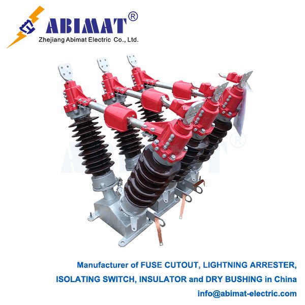
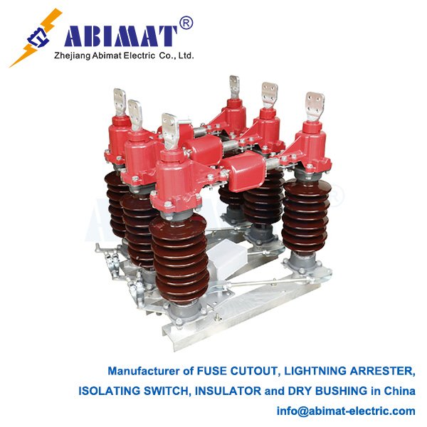
ABIMAT surge arresters are ubiquitous throughout electrical systems:
High Voltage Transmission & Substations: Protecting transformers, circuit breakers, buswork, and other primary equipment from lightning and switching surges. These are typically station-class arresters.
Medium Voltage Distribution: Safeguarding feeders, pole-mounted transformers, switchgear, and capacitors. Distribution-class arresters are common.
Low Voltage Systems: Protecting buildings, industrial control systems, data centers, and sensitive electronic equipment at the service entrance and point-of-use levels (SPDs). These often incorporate additional technologies like gas discharge tubes.
Selection & Maintenance
Proper selection involves matching the arrester’s Ur, Uc, Up, and energy capability to the system voltage, insulation levels (BIL/SIL), and the anticipated surge environment (location, lightning density). Regular maintenance, including visual inspections for damage or pollution, thermographic scanning for hot spots indicating degradation, and periodic leakage current monitoring, is essential to ensure continued reliability.
Conclusion
Electrical surge arresters are indispensable guardians of modern electrical infrastructure. By reliably clamping transient overvoltages and diverting destructive surge currents to ground, they prevent equipment failure, enhance system reliability, minimize downtime, and protect significant investments. Understanding their operating principles, key technologies, and critical parameters is fundamental for engineers designing, operating, and maintaining safe and resilient power systems and electronic installations. Continuous advancements in MOV technology and polymeric housing design further improve their performance, longevity, and safety.