Essential Protection: The Role of 66kV Surge Arresters
Within electrical power systems operating at 66kV, surge arresters are critical protective devices. Installed at substations, along transmission lines, and near sensitive equipment, their primary function is safeguarding transformers, switchgear, circuit breakers, and other vital assets from destructive voltage surges.
The Nature of Voltage Surges
Voltage surges are transient overvoltages, typically lasting microseconds, originating from:
- Lightning: Direct strikes to lines or structures, or induced voltages from nearby strikes.
- Switching Operations: Energizing or de-energizing lines, capacitor banks, or transformers; interrupting fault currents.
- System Faults: Ground faults or phase-to-phase faults.
These events can generate voltages significantly exceeding the system’s nominal 66kV (RMS phase-to-phase) and the equipment’s Basic Insulation Level (BIL). Without mitigation, such surges cause insulation failure, equipment damage, and costly outages.
Core Technology: Metal-Oxide Varistors (MOV)
Modern 66kV surge arresters rely primarily on Zinc Oxide (ZnO) Metal-Oxide Varistors. Under normal operating voltage (typically 40-45kV RMS line-to-ground), the MOV blocks exhibit extremely high resistance, conducting only minimal leakage current. When a surge exceeds the arrester’s triggering voltage, the MOV’s resistance drops dramatically within nanoseconds. This creates a low-impedance path to earth, safely diverting the surge current around the protected equipment. Once the surge passes, the arrester rapidly returns to its high-resistance state, restoring normal operation.
Key Technical Specifications
Selecting and applying 66kV arresters requires careful attention to these parameters:
Rated Voltage (Ur): The maximum permissible continuous power-frequency voltage (RMS) the arrester can withstand during specified temporary overvoltage (TOV) conditions. Common Ur values for 66kV systems are 60kV or 66kV.
Continuous Operating Voltage (Uc): The maximum permissible continuous power-frequency voltage (RMS) across the arrester terminals under steady-state conditions. This must exceed the system’s maximum continuous line-to-ground voltage.
Nominal Discharge Current (In): The peak value of the standard 8/20 µs current wave used for classifying the arrester’s duty class (e.g., 10kA, 20kA). Higher ratings indicate greater energy handling capacity.
Residual Voltage (Ur): The peak voltage measured across the arrester terminals when discharging the nominal discharge current (In). This value must be lower than the BIL of the protected equipment. Lower residual voltage indicates superior protection.
Pressure Relief Class: Ensures the arrester safely vents internal gases during catastrophic failure without violent rupture.
Creepage Distance: Essential for maintaining performance in polluted environments.
Application and Installation
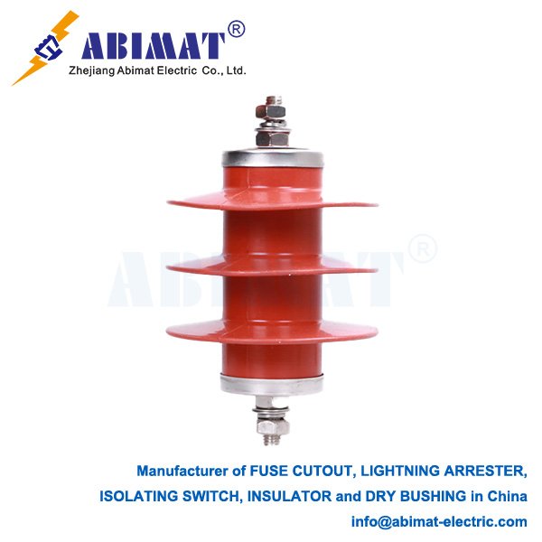
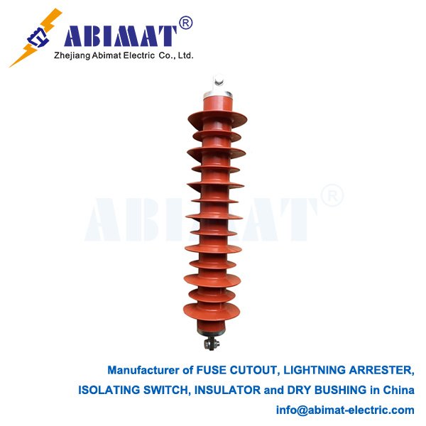
Robustly constructed with porcelain or polymer housings for outdoor durability, 66kV arresters are typically installed:
Directly adjacent to transformers (on the line side).
At substation line entrances and on critical busbars.
On overhead lines susceptible to lightning.
At transitions between overhead lines and underground cables.
A low-impedance connection to a well-designed grounding system is essential for effective surge energy dissipation.
Maintenance Considerations
While the Abimat modern arresters are largely maintenance-free, periodic visual inspections for physical damage, contamination, or surface tracking are prudent. Leakage current monitoring devices can provide early indications of potential MOV degradation or moisture ingress.