Line Disconnect Switch: Function and Application in Power Systems
Line disconnect switches—people also call them isolators—are basic mechanical switching devices we use in electrical power systems. Their main job is to create a safe, visible air gap. We use this gap to isolate a circuit or equipment from the power source. This isolation lets us do maintenance, repairs, or reroute power. They’re critical components; they keep workers safe and help the network run reliably.
Key Function: Isolation, Not Load Breaking
We need to tell the difference between disconnect switches and circuit breakers clearly. We don’t design disconnect switches to cut off load current or fault current. We only use them on circuits that an upstream circuit breaker has already de-energized. If we try to open a switch when it’s carrying load, it can create a dangerous electric arc. This arc can damage equipment and cause serious safety risks. The switch’s only purpose is to give a reliable, visible open point. This point lets us confirm a section of the line is de-energized and grounded—so we can work safely.
Common Types and Configurations
We use different designs depending on the voltage level and what we need the switch for.
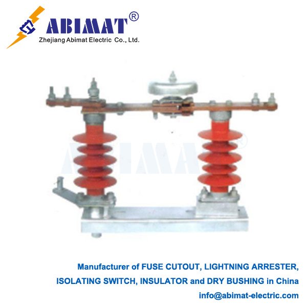
The horizontal-swing type is the most common one in substations. Its blade rotates horizontally to open or close the circuit.
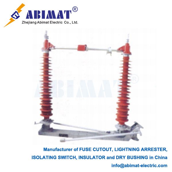
Then there’s the vertical-break type. Its blade moves up and down, and we often use it where space is tight.
The center-break type has two rotating blades. These blades separate from the center, and this gives two breaks in a row for higher voltage uses.
We can operate these switches manually—using a rotating handle and an insulating rod—or with a motor for remote control.
Critical Components and Features
A regular disconnect switch has three main parts.
First is the current-carrying path. It has main blades and contacts, and these parts are made to carry the full system current nonstop.
Next are the insulators. They hold up the live parts and keep them electrically isolated from the grounded structure.
Then there’s the operating mechanism. It’s either a manual system or a motorized one, and it opens or closes the blades.
Many switches also have auxiliary contacts. These connect to the substation’s control system. They show if the switch is open or closed, and they stop unsafe operating steps.
Applications and Selection Criteria